Monday, May 19, 2008

protect your network wireless

Protecting Your Wireless Network

A home wireless network can be incredibly useful and convenient, but it’s a new concept in home networking that needs new security solutions.

Check out our guide to Wireless Protection below:

Wireless network security

When you set up a wireless network in your house, the broadband signal is sent out from your router – it’s no longer necessary to physically connect to your network, and your network is no longer contained by the walls of your house. While this is really convenient for you, it creates a whole new set of security challenges. But protecting your wireless network is essential if you want to keep your connection private and hacker-free.

How do I check if my wireless network has security?

Go to My Network Places and scan for your wireless network. In the list that appears, there should be a picture of a padlock next to the name of your network. If there is no padlock, then you need security.

One of the threats to your wireless network is that other users might log on. At best, this means they can use your connection and slow it down, and at worst they can hack into your personal files.

What security methods are available?

You need a wireless encryption key. This is a series of numbers and letters, working like a password turning data into a code before transmission and making hacking more difficult. The most commonly used methods are:

  • WEP with 64bit or 128bit encryption strength – a simple 64 or 128Bit encryption but offers limited security and is relatively easy to break.
  • WPA-PSK (WPA-Personal) - in the forms of WPA-TKIP which offers better security and is backwards compatible with older routers and USB keys, and WPA2-AES which offers the best security and performance but less compatibility.

Is there anything else I can do?

As well as having an encryption key, there are a few other ways of protecting yourself when you go wireless:

  • Firewall – either built into your router or as software on your PC, this will help to protect you from hackers
  • Anti-virus software – such as Norton or McAfee, to protect you from computer viruses
  • Anti-spyware software – to prevent spyware from collecting personal information about you
  • Anti-phishing – to alert you if you have gone to a listed fraudulent website

You should also regularly run live updates on windows and your anti-virus to ensure that your security is always up-to-date.

What is wireless isolation?

Wireless isolation takes your security to that extra level. It allows you to stop other PCs from detecting your wireless signal. This would hide the name of your signal service set identifier (SSID) meaning that the information on your network would be completely isolated. Wireless isolation is built in to some routers but must be enabled by the user – check your router instructions for details.

What is an access list?

Access lists are basically an extra level of security on your network. As well as having to have the password for your network, users would also have to be on the access list. Your router’s instructions will explain how to isolate and filter a MAC address, which is what you need to create an access list.


source : http://www.broadbandchoices.co.uk/protecting-your-wireless-network.html


ip address subneting , network

IP addresses and subnets


Although IP stands for Internet Protocol, it's a communications protocol used from the smallest private network to the massive global Internet. An IP address is a unique identifier given to a single device on an IP network. The IP address consists of a 32-bit number that ranges from 0 to 4294967295. This means that theoretically, the Internet can contain approximately 4.3 billion unique objects. But to make such a large address block easier to handle, it was chopped up into four 8-bit numbers, or "octets," separated by a period. Instead of 32 binary base-2 digits, which would be too long to read, it's converted to four base-256 digits. Octets are made up of numbers ranging from 0 to 255. The numbers below show how IP addresses increment.

0.0.0.0
0.0.0.1
...increment 252 hosts...
0.0.0.254
0.0.0.255
0.0.1.0
0.0.1.1
...increment 252 hosts...
0.0.1.254
0.0.1.255
0.0.2.0
0.0.2.1
...increment 4+ billion hosts...
255.255.255.255

The word subnet is short for sub network--a smaller network within a larger one. The smallest subnet that has no more subdivisions within it is considered a single "broadcast domain," which directly correlates to a single LAN (local area network) segment on an Ethernet switch. The broadcast domain serves an important function because this is where devices on a network communicate directly with each other's MAC addresses, which don't route across multiple subnets, let alone the entire Internet. MAC address communications are limited to a smaller network because they rely on ARP broadcasting to find their way around, and broadcasting can be scaled only so much before the amount of broadcast traffic brings down the entire network with sheer broadcast noise. For this reason, the most common smallest subnet is 8 bits, or precisely a single octet, although it can be smaller or slightly larger.

Subnets have a beginning and an ending, and the beginning number is always even and the ending number is always odd. The beginning number is the "Network ID" and the ending number is the "Broadcast ID." You're not allowed to use these numbers because they both have special meaning with special purposes. The Network ID is the official designation for a particular subnet, and the ending number is the broadcast address that every device on a subnet listens to. Anytime you want to refer to a subnet, you point to its Network ID and its subnet mask, which defines its size. Anytime you want to send data to everyone on the subnet (such as a multicast), you send it to the Broadcast ID. Later in this article, I'll show you an easy mathematical and graphical way to determine the Network and Broadcast IDs.

The graphical subnet ruler


Over the years, as I watched people struggle with the subject of IP subnetting, I wanted a better way to teach the subject. I soon realized that many students in IT lacked the necessary background in mathematics and had a hard time with the concept of binary numbers. To help close this gap, I came up with the graphical method of illustrating subnets shown in Figure A. In this example, we're looking at a range of IP addresses from 10.0.0.0 up to 10.0.32.0. Note that the ending IP of 10.0.32.0 itself is actually the beginning of the next subnet. This network range ends at the number right before it, which is 10.0.31.255.

Figure A

Note that for every bit increase, the size of the subnet doubles in length, along with the number of hosts. The smallest tick mark represents 8 bits, which contains a subnet with 256 hosts--but since you can't use the first and last IP addresses, there are actually only 254 usable hosts on the network. The easiest way to compute how many usable hosts are in a subnet is to raise 2 to the power of the bit size minus 2. Go up to 9 bits ,and we're up to 510 usable hosts, because 2 to the 9th is 512, and we don't count the beginning and ending. Keep on going all the way up to 13 bits, and we're up to 8,190 usable hosts for the entire ruler shown above.

Learning to properly chop subnets


Subnets can be subdivided into smaller subnets and even smaller ones still. The most important thing to know about chopping up a network is that you can't arbitrarily pick the beginning and ending. The chopping must be along clean binary divisions. The best way to learn this is to look at my subnet ruler and see what's a valid subnet. In Figure B, green subnets are valid and red subnets are not.

Figure B

The ruler was constructed like any other ruler, where we mark it down the middle and bisect it. Then, we bisect the remaining sections and with shrinking markers every time we start a new round of bisecting. In the sample above, there were five rounds of bisections. If you look carefully at the edge of any valid (green) subnet blocks, you'll notice that none of the markers contained within the subnet is higher than the edge's markers. There is a mathematical reason for this, which we'll illustrate later, but seeing it graphically will make the math easier to understand.

The role of the subnet mask


The subnet mask plays a crucial role in defining the size of a subnet. Take a look at Figure C. Notice the pattern and pay special attention to the numbers in red. Whenever you're dealing with subnets, it will come in handy to remember eight special numbers that reoccur when dealing with subnet masks. They are 255, 254, 252, 248, 240, 224, 192, and 128. You'll see these numbers over and over again in IP networking, and memorizing them will make your life much easier.

Figure C

I've included three class sizes. You'll see the first two classes, with host bit length from 0 to 16, most often. It's common for DSL and T1 IP blocks to be in the 0- to 8-bit range. Private networks typically work in the 8- to 24-bit range.

Note how the binary mask has all those zeros growing from right to left. The subnet mask in binary form always has all ones to the left and all zeros to the right. The number of zeros is identical to the subnet length. I showed only the portion of the binary subnet in the octet that's interesting, since all octets to the right consist of zeros and all octets to the left consist of ones. So if we look at the subnet mask where the subnet length is 11 bits long, the full binary subnet mask is 11111111.11111111.11111000.00000000. As you can see under mask octet, the subnet mask transitions from 1 to 0 in the third octet. The particular binary subnet mask translates directly to base-256 form as 255.255.248.0.

The "mask" in subnet mask


The subnet mask not only determines the size of a subnet, but it can also help you pinpoint where the end points on the subnet are if you're given any IP address within that subnet. The reason it's called a subnet "mask" is that it literally masks out the host bits and leaves only the Network ID that begins the subnet. Once you know the beginning of the subnet and how big it is, you can determine the end of the subnet, which is the Broadcast ID.

To calculate the Network ID, you simply take any IP address within that subnet and run the AND operator on the subnet mask. Let's take an IP address of 10.20.237.15 and a subnet mask of 255.255.248.0. Note that this can be and often is written in shorthand as 10.20.237.15/21 because the subnet mask length is 21. Figure D and Figure E show the Decimal and Binary versions of the AND operation.

Figure D

Decimal math

Figure E

Binary math

The binary version shows how the 0s act as a mask on the IP address on top. Inside the masking box, the 0s convert all numbers on top into zeros, no matter what the number is. When you take the resultant binary Network ID and convert it to decimal, you get 10.20.232.0 as the Network ID.

One thing that's always bothered me about the way subnetting is taught is that students are not shown a simple trick to bypass the need for binary conversions when doing AND operations. I even see IT people in the field using this slow and cumbersome technique to convert everything to binary, run the AND operation, and then convert back to decimal using the Windows Calculator. But there's a really simple shortcut using the Windows Calculator, since the AND operator works directly on decimal numbers. Simply punch in 237, hit the AND operator, and then 248 and [Enter] to instantly get 232, as shown in Figure F. I'll never understand why this isn't explained to students, because it makes mask calculations a lot easier.

Figure F

Since there are 11 zeros in the subnet mask, the subnet is 11 bits long. This means there are 2^11, or 2,048, maximum hosts in the subnet and the last IP in this subnet is 10.20.239.255. You could compute this quickly by seeing there are three zeros in the third octet, which means the third octet of the IP address can have a variance of 2^3, or 8. So the next subnet starts at 10.20.232+8.0, which is 10.20.240.0. If we decrease that by 1, we have 10.20.239.255, which is where this subnet ends. To help you visualize this, Figure G shows it on my subnet ruler.

Figure G

IP classes made simple


For an arbitrary classification of IP subnets, the creators of the Internet chose to break the Internet into multiple classes. Note that these aren't important as far as your subnet calculations are concerned; this is just how the Internet is "laid out." The Internet is laid out as Class A, B, C, D, and E. Class A uses up the first half of the entire Internet, Class B uses half of the remaining half, Class C uses the remaining half again, Class D (Multicasting) uses up the remaining half again, and whatever is left over is reserved for Class E. I've had students tell me that they struggled with the memorization of IP classes for weeks until they saw this simple table shown in Figure H. This is because you don't actually need to memorize anything, you just learn the technique for constructing the ruler using half of what's available.

Figure H

Remember that all subnets start with EVEN numbers and all subnet endings are ODD. Note that 0.0.0.0/8 (0.0.0.0 to 0.255.255.255) isn't used and 127.0.0.0/8 (127.0.0.0 to 127.255.255.255) is reserved for loopback addresses.

All Class A addresses have their first octet between 1 to 126 because 0 and 127 are reserved. Class A subnets are all 24 bits long, which means the subnet mask is only 8 bits long. For example, we have the entire 3.0.0.0/8 subnet owned by GE, since GE was lucky enough to get in early to be assigned 16.8 million addresses. The U.S. Army owns 6.0.0.0/8. Level 3 Communications owns 8.0.0.0/8. IBM owns 9.0.0.0/8. AT&T owns 12.0.0.0/8. Xerox owns 13.0.0.0/8. HP owns 15.0.0.0/8 and 16.0.0.0/8. Apple owns 17.0.0.0/8.

All Class B addresses have their first octet between 128 and 191. Class B subnets are all 16 bits long, which means the subnet masks are 16 bits long. For example, BBN Communications owns 128.1.0.0/16, which is 128.1.0.0 to 128.1.255.255. Carnegie Mellon University owns 128.2.0.0/16.

All Class C addresses have their first octet between 192 and 223. Class C subnets are all 8 bits long, so the subnet mask is only 24 bits long. Note that ARIN (the organization that assigns Internet addresses) will sell blocks of four Class C addresses only to individual companies and you have to really justify why you need 1,024 Public IP addresses. If you need to run BGP so you can use multiple ISPs for redundancy, you have to have your own block of IP addresses. Also note that this isn't the old days, where blocks of 16.8 million Class A addresses were handed out for basically nothing. You have to pay an annual fee for your block of 1,024 addresses with a subnet mask of /22, or 255.255.252.0.

The concept of subnet classes can cause harm in actual practice. I've actually seen people forget to turn classes off in their old Cisco router and watch large subnet routes get hijacked on a large WAN configured for dynamic routing whenever some routes were added. This is because a Cisco router will assume the subnet mask is the full /8 or /16 or /24 even if you define something in between. All newer Cisco IOS software versions turn off the concept of subnet classes and uses classless routing by default. This is done with the default command "IP Classless."

Public versus private IP addresses


Besides the reserved IP addresses (0.0.0.0/8 and 127.0.0.0/8) mentioned above, there are other addresses not used on the public Internet. These private subnets consist of private IP addresses and are usually behind a firewall or router that performs NAT (network address translation). NAT is needed because private IP addresses are nonroutable on the public Internet, so they must be translated into public IP addresses before they touch the Internet. Private IPs are never routed because no one really owns them. And since anyone can use them, there's no right place to point a private IP address to on the public Internet. Private IP addresses are used in most LAN and WAN environments, unless you're lucky enough to own a Class A or at least a Class B block of addresses, in which case you might have enough IPs to assign internal and external IP addresses.

The following blocks of IP addresses are allocated for private networks:

  • 10.0.0.0/8 (10.0.0.0 to 10.255.255.255)
  • 172.16.0.0/12 (172.16.0.0 to 172.31.255.255)
  • 192.168.0.0/16 (192.168.0.0 to 192.168.255.255)
  • 169.254.0.0/16 (169.254.0.0 to 169.254.255.255)*

*Note that 169.254.0.0/16 is a block of private IP addresses used for random self IP assignment where DHCP servers are not available.

10.0.0.0/8 is normally used for larger networks, since there are approximately 16.8 million IP addresses available within that block. They chop it up into lots of smaller groups of subnets for each geographic location, which are then subdivided into even smaller subnets. Smaller companies typically use the 172.16.0.0/12 range, chopped up into smaller subnets, although there's no reason they can't use 10.0.0.0/8 if they want to. Home networks typically use a /24 subnet within the 192.168.0.0/16 subnet.

The use of private IP addresses and NAT has prolonged the life of IPv4 for the foreseeable future because it effectively allows a single public IP address to represent thousands of private IP addresses. At the current rate that IPv4 addresses are handed out, we have enough IPv4 addresses for approximately 17 years. ARIN is much more stingy now about handing them out, and small blocks of IP addresses are relatively expensive compared to the old days, when companies like Apple were simply handed a block of 16.8 million addresses. The next version of IP addresses, called IPv6, is 128 bits long--and there are more than 79 thousand trillion trillion times more IP addresses than IPv4. Even if you assigned 4.3 billion people on the planet with 4.3 billion IP addresses each, you would still have more than 18 million trillion IPv6 addresses left!

Setting up MikroTik RouterOS™

Setting up MikroTik RouterOS™

Description

Downloading and Installing the MikroTik RouterOS™

The download and installation process of the MikroTik RouterOS™ is described in the following diagram:

downloading and Installing

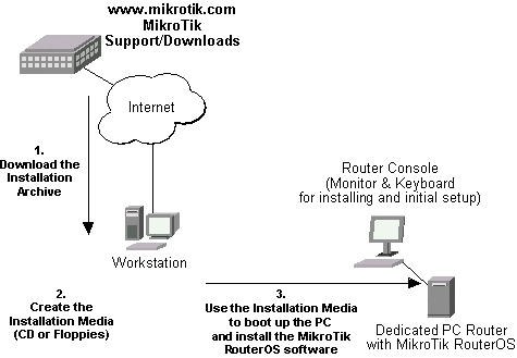
  1. Download the basic installation archieve file.

    Depending on the desired media to be used for installing the MikroTik RouterOS™ please chose one of the following archive types for downloading:

    • ISO image - of the installation CD, if you have a CD writer for creating CDs. The ISO image is in the MTcdimage_v2-9-x_dd-mmm-yyyy_(build_z).zip archive file containing a bootable CD image. The CD will be used for booting up the dedicated PC and installing the MikroTik RouterOS™ on its hard-drive or flash-drive.
    • Netinstall - if you want to install RouterOS over a LAN with one floppy boot disk, or alternatively using PXE or EtherBoot option supported by some network interface cards, that allows truly networked installation. Netinstall program works on Windows 95/98/NT4/2K/XP.
    • MikroTik Disk Maker - if you want to create 3.5" installation floppies. The Disk Maker is a self-extracting archive DiskMaker_v2-9-x_dd-mmm-yyyy_(build_z).exe file, which should be run on your Windows 95/98/NT4/2K/XP workstation to create the installation floppies. The installation floppies will be used for booting up the dedicated PC and installing the MikroTik RouterOS™ on its hard-drive or flash-drive.
  2. Create the installation media.

    Use the appropriate installation archive to create the Installation CD or floppies.

    • For the CD, write the ISO image onto a blank CD.
    • For the floppies, run the Disk Maker on your Windows workstation to create the installation floppies. Follow the instructions and insert the floppies in your FDD as requested, label them as Disk 1,2,3, etc.
  3. Install the MikroTik RouterOS™ software.

    Your dedicated PC router hardware should have:

    • CPU and motherboard - advanced 4th generation (core frequency 100MHz or more), 5th generation (Intel Pentium, Cyrix 6X86, AMD K5 or comparable) or newer uniprocessor Intel IA-32 (i386) compatible (multiple processors are not supported)
    • RAM - minimum 64 MiB, maximum 1 GiB; 64 MiB or more recommended
    • Hard Drive/Flash - standard ATA interface controller and drive (SCSI and USB controllers and drives are not supported; RAID controllers that require additional drivers are not supported) with minimum of 64 Mb space

    Hardware needed for installation time only

    Depending on installation method chosen the router must have the following hardware:

    • Floppy-based installation - standard AT floppy controller and 3.5'' disk drive connected as the first floppy disk drive (A); AT, PS/2 or USB keyboard; VGA-compatible video controller card and monitor
    • CD-based installation - standard ATA/ATAPI interface controller and CD drive supporting "El Torito" bootable CDs (you might need also to check if the router's BIOS supports booting from this type of media; if El Torito is not supported by the BIOS, you can still boot up from the CD using Smart Boot Manager Floppy); AT, PS/2 or USB keyboard; VGA-compatible video controller card and monitor
    • Floppy-based network installation - standard AT floppy controller and 3.5'' disk drive connected as the first floppy disk drive (A); PCI Ethernet network interface card supported by MikroTik RouterOS (see the Device Driver List for the list)
    • Full network-based installation - PCI Ethernet network interface card supported by MikroTik RouterOS (see the Device Driver List for the list) with PXE or EtherBoot extension booting ROM (you might need also to check if the router's BIOS supports booting from network)

    Note that if you use Netinstall, you can license the software during the installation procedure (the next point of this section describes how to do it).

    Boot up your dedicated PC router from the Installation Media you created and follow the instructions on the console screen while the HDD is reformatted and MikroTik RouterOS installed on it. After successful installation please remove the installation media from your CD or floppy disk drive and hit 'Enter' to reboot the router.

  4. License the software.

    When booted, the software allows you to use all its features for 24 hours (note that you can pause the countdown by shutting down the router). If the license key will not be entered during this period of time, the router will become unusable, and will need a complete reinstallation.

    RouterOS licensing scheme is based on software IDs. To license the software, you must know the software ID. It is shown during installation procedures, and also you can get it from system console or Winbox. To get the software ID from system console, type: /system license print (note that you must first log in the router; by default there is user admin with no password (just press [Enter] key when prompted for password)). See sections below on basic configuration of your router

    Once you have the ID, you can obtain a license:

    • You should have an account on our account server. If you do not have an account at www.mikrotik.com, just press the 'New' button on the upper right-hand corner of the MikroTik's web page to create your account
    • Choose the appropriate licence level that meets your needs. Please see the License Manual or the Software price list. Note that there is a free license with restricted features (no time limitation)
    • There are different methods how to get a license from the account server:

      1. Enter the software ID in the account server, and get the license key by e-mail. You can upload the file received on the router's FTP server, or drag-and-drop it into opened Winbox window
      2. You can open the file with a text editor, and copy the contents. Then paste the text into system console (in any menu - you just should be logged in), or into System->License window of Winbox
      3. If the router has Internet connection, you can obtain the license directly from within it. The commands are described in the License Manual. Note that you must have Allow to use my account in netinstall option enabled for your account. You can set it by following change user information link on the main screen of the account server.

Notes

The hard disk will be entirely reformatted during the installation and all data on it will be lost!

You can move the hard drive with MikroTik RouterOS installed to a new hardware without loosing a license, but you cannot move the RouterOS to a different hard drive without purchasing an another license (except hardware failure situations). For additional information write to key-support@mikrotik.com.

Note! Do not use MS-DOS format command or other disk format utilities to reinstall your MikroTik router! This will cause the Software-ID to change, so you will need to buy another license in order to get MikroTik RouterOS running.

Logging into the MikroTik Router

Description

Normally you connect to the router by IP addresses with any telnet or SSH client software (a simple text-mode telnet client is usually called telnet and is distributed together with almost any OS). You can also use graphical configuration tool for Windows (also can be run in Linux using Wine) called Winbox. To get Winbox, connect to the router's IP address with a web browser, and follow the link to download winbox.exe from the router.

MAC-telnet is used to connect to a router when there is no other way to connect to it remotely if the router has no IP address or in case of misconfigured firewall. MAC-telnet can only be used from the same broadcast domain (so there should be no routers in between) as any of the router's enabled interfaces (you can not connect to a disabled interface). MAC-telnet program is a part of the Neighbor Viewer. Download it from www.mikrotik.com, unpack both files contained in the archive to the same directory, and run NeighborViewer.exe. A list of MikroTik routers working in the same broadcast domain will be showed double-click the one you need to connect to. Note that Winbox is also able to connect to routers by their MAC addresses, and has the discovery tool built-in.

You can also connect to the router using a standard DB9 serial null-modem cable from any PC. Default settings of the router's serial port are 9600 bits/s (for RouterBOARD 500 series - 115200 bits/s), 8 data bits, 1 stop bit, no parity, hardware (RTS/CTS) flow control. Use terminal emulation program (like HyperTerminal or SecureCRT in Windows, or minicom in UNIX/Linux) to connect to the router. The router will beep twice when booted up, and you should see the login prompt shortly before that (check cabling and serial port settings if you do not see anything in the terminal window).

When logging into the router via terminal console, you will be presented with the MikroTik RouterOS™ login prompt. Use 'admin' and no password (hit [Enter]) for logging in the router for the first time, for example:

MikroTik v2.9
Login: admin
Password:

The password can be changed with the /password command.

[admin@MikroTik] > password
old password:
new password: ************
retype new password: ************
[admin@MikroTik] >

Adding Software Packages

Description

The basic installation comes only with the system package. This includes basic IP routing and router administration. To have additional features such as IP Telephony, OSPF, wireless and so on, you will need to download additional software packages.

The additional software packages should have the same version as the system package. If not, the package won't be installed. Please consult the MikroTik RouterOS™ Software Package Installation and Upgrading Manual for more detailed information about installing additional software packages.

To upgrade the router packages, simply upload the packages to the router via ftp, using the binary transfer mode. After you have uploaded the packages, reboot the router, and the features that are provided by those packages will be available (regarding your license type, of course).

Navigating The Terminal Console

Description

Welcome Screen and Command Prompt

After logging into the router you will be presented with the MikroTik RouterOS™ Welcome Screen and command prompt, for example:

 
MMM MMM KKK TTTTTTTTTTT KKK
MMMM MMMM KKK TTTTTTTTTTT KKK
MMM MMMM MMM III KKK KKK RRRRRR OOOOOO TTT III KKK KKK
MMM MM MMM III KKKKK RRR RRR OOO OOO TTT III KKKKK
MMM MMM III KKK KKK RRRRRR OOO OOO TTT III KKK KKK
MMM MMM III KKK KKK RRR RRR OOOOOO TTT III KKK KKK

MikroTik RouterOS 2.9 (c) 1999-2004 http://www.mikrotik.com/


Terminal xterm detected, using multiline input mode
[admin@MikroTik] >

The command prompt shows the identity name of the router and the current menu level, for example:

[admin@MikroTik] >
[admin@MikroTik] interface>
[admin@MikroTik] ip address>
Commands

The list of available commands at any menu level can be obtained by entering the question mark '?', for example:

[admin@MikroTik] >

log/ -- System logs
quit -- Quit console
radius/ -- Radius client settings
certificate/ -- Certificate management
special-login/ -- Special login users
redo -- Redo previously undone action
driver/ -- Driver management
ping -- Send ICMP Echo packets
setup -- Do basic setup of system
interface/ -- Interface configuration
password -- Change password
undo -- Undo previous action
port/ -- Serial ports
import -- Run exported configuration script
snmp/ -- SNMP settings
user/ -- User management
file/ -- Local router file storage.
system/ -- System information and utilities
queue/ -- Bandwidth management
ip/ -- IP options
tool/ -- Diagnostics tools
ppp/ -- Point to Point Protocol
routing/ -- Various routing protocol settings
export --

[admin@MikroTik] >
[admin@MikroTik] ip>


.. -- go up to root
service/ -- IP services
socks/ -- SOCKS version 4 proxy
arp/ -- ARP entries management
upnp/ -- Universal Plug and Play
dns/ -- DNS settings
address/ -- Address management
accounting/ -- Traffic accounting
the-proxy/ --
vrrp/ -- Virtual Router Redundancy Protocol
pool/ -- IP address pools
packing/ -- Packet packing settings
neighbor/ -- Neighbors
route/ -- Route management
firewall/ -- Firewall management
dhcp-client/ -- DHCP client settings
dhcp-relay/ -- DHCP relay settings
dhcp-server/ -- DHCP server settings
hotspot/ -- HotSpot management
ipsec/ -- IP security
web-proxy/ -- HTTP proxy
export --

[admin@MikroTik] ip>

The list of available commands and menus has short descriptions next to the items. You can move to the desired menu level by typing its name and hitting the [Enter] key, for example:

[admin@MikroTik] >                 | Base level menu
[admin@MikroTik] > driver | Enter 'driver' to move to the driver
| level menu
[admin@MikroTik] driver> / | Enter '/' to move to the base level menu
| from any level
[admin@MikroTik] > interface | Enter 'interface' to move to the
| interface level menu
[admin@MikroTik] interface> /ip | Enter '/ip' to move to the IP level menu
| from any level
[admin@MikroTik] ip> |

A command or an argument does not need to be completed, if it is not ambiguous. For example, instead of typing interface you can type just in or int. To complete a command use the [Tab] key. Note that the completion is optional, and you can just use short command and parameter names

The commands may be invoked from the menu level, where they are located, by typing its name. If the command is in a different menu level than the current one, then the command should be invoked using its full (absolute) or relative path, for example:

[admin@MikroTik] ip route> print                | Prints the routing table
[admin@MikroTik] ip route> .. address print | Prints the IP address table
[admin@MikroTik] ip route> /ip address print | Prints the IP address table

The commands may have arguments. The arguments have their names and values. Some commands, may have a required argument that has no name.

Summary on executing the commands and navigating the menus
Command Action
command [Enter] Executes the command
[?] Shows the list of all available commands
command [?] Displays help on the command and the list of arguments
command argument [?] Displays help on the command's argument
[Tab] Completes the command/word. If the input is ambiguous, a second [Tab] gives possible options
/ Moves up to the base level
/command Executes the base level command
.. Moves up one level
"" Specifies an empty string
"word1 word2" Specifies a string of 2 words that contain a space

You can abbreviate names of levels, commands and arguments.

For the IP address configuration, instead of using the address and netmask arguments, in most cases you can specify the address together with the number of true bits in the network mask, i.e., there is no need to specify the netmask separately. Thus, the following two entries would be equivalent:

/ip address add address 10.0.0.1/24 interface ether1
/ip address add address 10.0.0.1 netmask 255.255.255.0 interface ether1

Notes

You must specify the size of the network mask in the address argument, even if it is the 32-bit subnet, i.e., use 10.0.0.1/32 for address=10.0.0.1 netmask=255.255.255.255

Basic Configuration Tasks

Description

Interface Management

Before configuring the IP addresses and routes please check the /interface menu to see the list of available interfaces. If you have Plug-and-Play cards installed in the router, it is most likely that the device drivers have been loaded for them automatically, and the relevant interfaces appear on the /interface print list, for example:

[admin@MikroTik] interface> print
Flags: X - disabled, D - dynamic, R - running
# NAME TYPE RX-RATE TX-RATE MTU
0 R ether1 ether 0 0 1500
1 R ether2 ether 0 0 1500
2 X wavelan1 wavelan 0 0 1500
3 X prism1 wlan 0 0 1500
[admin@MikroTik] interface>

The interfaces need to be enabled, if you want to use them for communications. Use the /interface enable name command to enable the interface with a given name or number, for example:

[admin@MikroTik] interface> print
Flags: X - disabled, D - dynamic, R - running
# NAME TYPE RX-RATE TX-RATE MTU
0 X ether1 ether 0 0 1500
1 X ether2 ether 0 0 1500
[admin@MikroTik] interface> enable 0
[admin@MikroTik] interface> enable ether2
[admin@MikroTik] interface> print
Flags: X - disabled, D - dynamic, R - running
# NAME TYPE RX-RATE TX-RATE MTU
0 R ether1 ether 0 0 1500
1 R ether2 ether 0 0 1500
[admin@MikroTik] interface>

The interface name can be changed to a more descriptive one by using /interface set command:

[admin@MikroTik] interface> set 0 name=Local; set 1 name=Public
[admin@MikroTik] interface> print
Flags: X - disabled, D - dynamic, R - running
# NAME TYPE RX-RATE TX-RATE MTU
0 R Local ether 0 0 1500
1 R Public ether 0 0 1500
[admin@MikroTik] interface>

Notes

The device drivers for NE2000 compatible ISA cards need to be loaded using the add command under the /drivers menu. For example, to load the driver for a card with IO address 0x280 and IRQ 5, it is enough to issue the command:

[admin@MikroTik] driver> add name=ne2k-isa io=0x280
[admin@MikroTik] driver> print
Flags: I - invalid, D - dynamic
# DRIVER IRQ IO MEMORY ISDN-PROTOCOL
0 D RealTek 8139
1 D Intel EtherExpressPro
2 D PCI NE2000
3 ISA NE2000 280
4 Moxa C101 Synchronous C8000
[admin@MikroTik] driver>

There are some other drivers that should be added manually. Please refer to the respective manual sections for the detailed information on how drivers are to be loaded.

Setup Command

Command name: /setup

Description

The initial setup of the router can be done by using the /setup command which offers the following configuration:

  • reset all router configuration
  • load interface driver
  • configure ip address and gateway
  • setup dhcp client
  • setup dhcp server
  • setup pppoe client
  • setup pptp client

Configure IP address on router, using the Setup command

Execute the /setup command from command line:

[admin@MikroTik] > setup
Setup uses Safe Mode. It means that all changes that are made during setup
are reverted in case of error, or if [Ctrl]+[C] is used to abort setup. To keep
changes exit setup using the [X] key.

[Safe Mode taken]
Choose options by pressing one of the letters in the left column, before
dash. Pressing [X] will exit current menu, pressing Enter key will select the
entry that is marked by an '*'. You can abort setup at any time by pressing
[Ctrl]+[C].
Entries marked by '+' are already configured.
Entries marked by '-' cannot be used yet.
Entries marked by 'X' cannot be used without installing additional packages.
r - reset all router configuration
+ l - load interface driver
* a - configure ip address and gateway
d - setup dhcp client
s - setup dhcp server
p - setup pppoe client
t - setup pptp client
x - exit menu
your choice [press Enter to configure ip address and gateway]: a

To configure IP address and gateway, press a or [Enter], if the a choice is marked with an asterisk symbol ('*').

 * a - add ip address
- g - setup default gateway
x - exit menu
your choice [press Enter to add ip address]: a

Choose a to add an IP address. At first, setup will ask you for an interface to which the address will be assigned. If the setup offers you an undesirable interface, erase this choice, and press the [Tab] key twice to see all available interfaces. After the interface is chosen, assign IP address and network mask on it:

your choice: a
enable interface:
ether1 ether2 wlan1
enable interface: ether1
ip address/netmask: 10.1.0.66/24
#Enabling interface
/interface enable ether1
#Adding IP address
/ip address add address=10.1.0.66/24 interface=ether1 comment="added by setup"
+ a - add ip address
* g - setup default gateway
x - exit menu
your choice: x

Basic Examples

Example

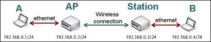
Assume you need to configure the MikroTik router for the following network setup:

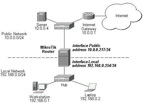
In the current example we use two networks:

  • The local LAN with network address 192.168.0.0 and 24-bit netmask: 255.255.255.0. The router's address is 192.168.0.254 in this network
  • The ISP's network with address 10.0.0.0 and 24-bit netmask 255.255.255.0. The router's address is 10.0.0.217 in this network

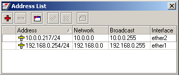
The addresses can be added and viewed using the following commands:

[admin@MikroTik] ip address> add address 10.0.0.217/24 interface Public
[admin@MikroTik] ip address> add address 192.168.0.254/24 interface Local
[admin@MikroTik] ip address> print
Flags: X - disabled, I - invalid, D - dynamic
# ADDRESS NETWORK BROADCAST INTERFACE
0 10.0.0.217/24 10.0.0.217 10.0.0.255 Public
1 192.168.0.254/24 192.168.0.0 192.168.0.255 Local
[admin@MikroTik] ip address>

Here, the network mask has been specified in the value of the address argument. Alternatively, the argument 'netmask' could have been used with the value '255.255.255.0'. The network and broadcast addresses were not specified in the input since they could be calculated automatically.

Please note that the addresses assigned to different interfaces of the router should belong to different networks.

Viewing Routes

You can see two dynamic (D) and connected (C) routes, which have been added automatically when the addresses were added in the example above:

[admin@MikroTik] ip route> print
Flags: A - active, X - disabled, I - invalid, D - dynamic, C - connect,
S - static, r - rip, b - bgp, o - ospf, d - dynamic
# DST-ADDRESS G GATEWAY DISTANCE INTERFACE
0 ADC 192.168.0.0/24 r 0.0.0.0 0 Local
1 ADC 10.0.0.0/24 r 0.0.0.0 0 Public
[admin@MikroTik] ip route> print detail
Flags: A - active, X - disabled, I - invalid, D - dynamic, C - connect,
S - static, r - rip, b - bgp, o - ospf, d - dynamic
0 ADC dst-address=192.168.0.0/24 prefsrc=192.168.0.254 interface=Local scope=10

1 ADC dst-address=10.0.0.0/24 prefsrc=10.0.0.217 interface=Public scope=10

[admin@MikroTik] ip route>

These routes show, that IP packets with destination to 10.0.0.0/24 would be sent through the interface Public, whereas IP packets with destination to 192.168.0.0/24 would be sent through the interface Local. However, you need to specify where the router should forward packets, which have destination other than networks connected directly to the router.

Adding Default Routes

In the following example the default route (destination 0.0.0.0 (any), netmask 0.0.0.0 (any)) will be added. In this case it is the ISP's gateway 10.0.0.1, which can be reached through the interface Public

[admin@MikroTik] ip route> add gateway=10.0.0.1
[admin@MikroTik] ip route> print
Flags: X - disabled, I - invalid, D - dynamic, J - rejected,
C - connect, S - static, R - rip, O - ospf, B - bgp
# DST-ADDRESS G GATEWAY DISTANCE INTERFACE
0 ADC 192.168.0.0/24 Local
1 ADC 10.0.0.0/24 Public
2 A S 0.0.0.0/0 r 10.0.0.1 0 Public
[admin@MikroTik] ip route>

Here, the default route is listed under #2. As we see, the gateway 10.0.0.1 can be reached through the interface 'Public'. If the gateway was specified incorrectly, the value for the argument 'interface' would be unknown.

Notes

You cannot add two routes to the same destination, i.e., destination-address/netmask! It applies to the default routes as well. Instead, you can enter multiple gateways for one destination. For more information on IP routes, please read the Routes, Equal Cost Multipath Routing, Policy Routing manual.

If you have added an unwanted static route accidentally, use the remove command to delete the unneeded one. You will not be able to delete dynamic (DC) routes. They are added automatically and represent routes to the networks the router connected directly.

Testing the Network Connectivity

From now on, the /ping command can be used to test the network connectivity on both interfaces. You can reach any host on both connected networks from the router.

How the /ping command works:

[admin@MikroTik] ip route> /ping 10.0.0.4
10.0.0.4 64 byte ping: ttl=255 time=7 ms
10.0.0.4 64 byte ping: ttl=255 time=5 ms
3 packets transmitted, 3 packets received, 0% packet loss
round-trip min/avg/max = 5/5.6/7 ms
[admin@MikroTik] ip route>
[admin@MikroTik] ip route> /ping 192.168.0.1
192.168.0.1 64 byte ping: ttl=255 time=1 ms
3 packets transmitted, 3 packets received, 0% packet loss
round-trip min/avg/max = 1/1.0/1 ms
[admin@MikroTik] ip route>

The workstation and the laptop can reach (ping) the router at its local address 192.168.0.254, If the router's address 192.168.0.254 is specified as the default gateway in the TCP/IP configuration of both the workstation and the laptop, then you should be able to ping the router:

C:\>ping 192.168.0.254
Reply from 192.168.0.254: bytes=32 time=10ms TTL=253
Reply from 192.168.0.254: bytes=32 time<10ms TTL=253

C:\>ping 10.0.0.217
Reply from 10.0.0.217: bytes=32 time=10ms TTL=253
Reply from 10.0.0.217: bytes=32 time<10ms TTL=253

C:\>ping 10.0.0.4
Request timed out.
Request timed out.
Request timed out.

Notes

You cannot access anything beyond the router (network 10.0.0.0/24 and the Internet), unless you do the one of the following:

  • Use source network address translation (masquerading) on the MikroTik router to 'hide' your private LAN 192.168.0.0/24 (see the information below), or
  • Add a static route on the ISP's gateway 10.0.0.1, which specifies the host 10.0.0.217 as the gateway to network 192.168.0.0/24. Then all hosts on the ISP's network, including the server, will be able to communicate with the hosts on the LAN

To set up routing, it is required that you have some knowledge of configuring TCP/IP networks. We strongly recommend that you obtain more knowledge, if you have difficulties configuring your network setups.

Advanced Configuration Tasks

Description

Next will be discussed situation with 'hiding' the private LAN 192.168.0.0/24 'behind' one address 10.0.0.217 given to you by the ISP.

Application Example with Masquerading

If you want to 'hide' the private LAN 192.168.0.0/24 'behind' one address 10.0.0.217 given to you by the ISP, you should use the source network address translation (masquerading) feature of the MikroTik router. Masquerading is useful, if you want to access the ISP's network and the Internet appearing as all requests coming from the host 10.0.0.217 of the ISP's network. The masquerading will change the source IP address and port of the packets originated from the network 192.168.0.0/24 to the address 10.0.0.217 of the router when the packet is routed through it.

Masquerading conserves the number of global IP addresses required and it lets the whole network use a single IP address in its communication with the world.

To use masquerading, a source NAT rule with action 'masquerade' should be added to the firewall configuration:

[admin@MikroTik] ip firewall nat> add chain=srcnat action=masquerade out-interface=Public
[admin@MikroTik] ip firewall nat> print
Flags: X - disabled, I - invalid, D - dynamic
0 chain=srcnat out-interface=Public action=masquerade

Notes

Please consult Network Address Translation for more information on masquerading.

Example with Bandwidth Management

Assume you want to limit the bandwidth to 128kbps on downloads and 64kbps on uploads for all hosts on the LAN. Bandwidth limitation is done by applying queues for outgoing interfaces regarding the traffic flow. It is enough to add a single queue at the MikroTik router:

[admin@MikroTik] queue simple> add max-limit=64000/128000 interface=Local
[admin@MikroTik] queue simple> print
Flags: X - disabled, I - invalid, D - dynamic
0 name="queue1" target-address=0.0.0.0/0 dst-address=0.0.0.0/0
interface=Local queue=default/default priority=8 limit-at=0/0
max-limit=64000/128000 total-queue=default
[admin@MikroTik] queue simple>

Leave all other parameters as set by default. The limit is approximately 128kbps going to the LAN (download) and 64kbps leaving the client's LAN (upload).

Example with NAT

Assume we have moved the server in our previous examples from the public network to our local one:

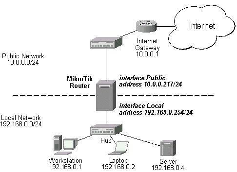
The server's address is now 192.168.0.4, and we are running web server on it that listens to the TCP port 80. We want to make it accessible from the Internet at address:port 10.0.0.217:80. This can be done by means of Static Network Address translation (NAT) at the MikroTik Router. The Public address:port 10.0.0.217:80 will be translated to the Local address:port 192.168.0.4:80. One destination NAT rule is required for translating the destination address and port:

[admin@MikroTik] ip firewall nat> add chain=dstnat action=dst-nat protocol=tcp dst-address=10.0.0.217/32
dst-port=80 to-addresses=192.168.0.4
[admin@MikroTik] ip firewall nat> pr
Flags: X - disabled, I - invalid, D - dynamic
0 chain=dstnat dst-address=10.0.0.217/32 protocol=tcp dst-port=80
action=dst-nat to-addresses=192.168.0.4 to-ports=0-65535

Notes

Please consult Network Address Translation for more information on Network Address Translation.


source : http://www.mikrotik.com/testdocs/ros/2.9/guide/basic.php

network t cp/ip


NETWORk TCP/IP

The Internet's open and efficient TCP/IP protocol is the foundation of an inter-networking design has made it the most widely used network protocol in the world.

The history of TCP/IP is like the protocol -- interdependent design and development conducted by several people and brought together as one. Following the design of TCP/IP by Robert Kahn and Vinton Cerf as described in the previous pages, DARPA contracted with three sites to develop operational versions:

  • BBN. A TENEX/PDP-10 implementation led by Ray Tomlinson and Bill Plummer.
  • Stanford. A BCPL/PDP-11 implementation led by Richard Karp from Cerf's group.

Four increasingly better versions of TCP/IP were developed -- TCP v1, TCP v2, a split into TCP v3 and IP v3 in the spring of 1978, and then stability with TCP v4 and IPv4 -- the standard protocol still in use on the Internet today.

In 1975, a two-network TCP/IP communications test was performed by establishment of a link between Stanford and University College London (UCL) systems through a Satellite Network (SATNET) connection. In November, 1977, a three-network TCP/IP test was conducted, successfully simulating complex, military-grade communications and verifying the inter-networking functionality inherent in the TCP/IP design:

  • An LSI-11 computer in a van driven down the San Francisco Bayshore Freeway sent the original data over a dual-rate 400/100 kbps spread spectrum Packet Radio Net to
  • A stationary ARPANET gateway at BBN in Boston, which sent the traffic over an internal ARPANET satellite link to
  • A computer in Norway, which sent the data over an ARPANET dedicated circuit to
  • UCL in London, England, which sent the data back across the ocean on the 64 kbps Packet Satellite Net using a shared channel on the Intelsat IV satellite to
  • BBN in Boston, when sent the data across the ARPANET to -
  • a DEC KA-10 computer at the University of Southern California Information Sciences Institute in Marina Del Ray.

Between 1978 and 1983, several TCP/IP research prototypes were developed on the systems listed below, proving the protocol's portability and ability to unify different systems:

System

Leads

Organization
IBM 360/370Bob BradenUCLA
LSI/11 (Packet Radio)Jim MathisSRI
MulticsDave ClarkMIT
PCDave ClarkMIT
PDP-9Peter KirsteinUCL
PDP-11 / BCPL Richard KarpStanford
Tenex/TOPS20Bill Plummer
Ray Tomlinson
BBN
UNIX / CMike WingfieldBBN
Unix / Macro11Jack HavertyBBN

The TCP/IP protocol was deployed to the ARPANET network with some persuasion, as noted in the emails at the top of the page. Not all sites were preparing to convert over their protocols, so Cerf, Jon Postel, and the TCP/IP team turned off the NCP network channel numbers on the ARPANET IMP's for a full day in mid 1982, so that only sites using TCP/IP could still operate. To emphasize the point, they disabled NCP again for two days later that fall. The full switchover to TCP/IP was performed on January 1, 1983, without too many problems, although a few recalcitrant sites were down as long as three months while they retrofitted their systems.

In 1984, the US Department of Defense made TCP/IP the standard for all military computer networking, which gave it a high profile and stable funding. In 1985, Dan Lynch and the Internet Architecture Board held a three day workshop on TCP/IP for the computer industry, which was attended by about 50 researchers and 250 vendor representatives. This meeting helped popularize knowledge of TCP/IP in the computer industry, and triggered the development of several TCP/IP networking products by different companies, starting the protocol on its way to become a commercial standard.

In September, 1988, Lynch organized an Internet convention that later became the Interop trade show. Fifty companies were invited to the first show to demonstrate interoperation of their TCP/IP packages, and five thousand engineers attended. The interoperability demonstration was successful, validating TCP/IP's open design and showing that the network standard could become a multi-vendor product. The Interop show grew tremendously over the next twelve years, held annually in a new location around the world.

TCP/IP, originally inspired by low-reliability wireless packet radio networks, has now become now the most reliable and widely deployed network in the world, and the IPv4 version developed in the 1970's remains the standard protocol in use on the Internet today.

IPv6. With the rapid growth of the Internet through the 1990's, there was a rapid reduction in the number of free IP addresses available under IPv4, which was never designed to scale to planetary levels. To get more addresses you need more bits, which means a longer IP address, which means a new architecture, which means changes to all of the TCP/IP routing software. In other words, a major change on which everyone needs to agree, and does not come about quickly.

After examining a number of proposals, the IETF settled on IPv6, recommended in January 1995 in RFC 1752, and sometimes called the Next Generation Internet Protocol, or IPng, or TCP/IP v6. Since then a number of organizations such as the IPV6 Forum have been working towards its widespread implementation.

By 2004, IPv6 was widely available from industry as an integrated TCP/IP protocol and supported by most new Internet networking equipment. Practical feedback began to be being received from experience with integration with existing TCP/IP v4 networks, for example as discussed in RFC 3901, DNS IPv6 Transport Operational Guidelines, and RFC 3974, IPv6 SMTP Operational Experience in Mixed IPv4/v6 Environments.

Resources. Additional information about the TCP/IP protocol can be found below:

  • IEN 151; Vinton Cerf; Final Report of the Stanford University TCP Project; 1 April 1980.
  • RFC 759; Jon Postel; Internet Message Protocol; August 1980.
  • RFC 760; Jon Postel; DoD Standard Internet Protocol; Jon Postel; January 1980.
  • RFC 761; Jon Postel; DoD Standard Transmission Control Protocol; Jan, 1980.
  • RFC 801; Jon Postel; NCP/TCP Transition Plan; Nov 1981.
  • RFC 1180; T. Socolofsky, C. Kale; A TCP/IP Tutorial; Jan 1991.
  • RFC 3449; H. Balakrishnan, V. N. Padmanabhan, G. Fairhurst, M. Sooriyabandara; TCP Performance Implications of Network Path Asymmetry; December 2002; BCP 69.

IPV6. Some RFC's related to TCP/IP v6 are listed below:

  • RFC 1886; DNS Extensions to support IP version 6; S. Thomson, C. Huitema; December 1995.
  • RFC 2460; Internet Protocol, Version 6 (IPv6) Specification; S. Deering; December 1998.
  • RFC 2893; Transition Mechanisms for IPv6 Hosts and Routers; R. Gilligan; August 2000.
  • RFC 3316; Internet Protocol Version 6 (IPv6) for Some Second and Third Generation Cellular Hosts; J. Arkko, G. Kuijpers, H. Soliman, J. Loughney, J. Wiljakka; April 2003.
  • RFC 3513; Internet Protocol Version 6 (IPv6) Addressing Architecture; R. Hinden; S. Deering; April 2003.

setting mikrotik bridge

Setting Mikrotik Wireless Brigde


Sering kali, kita ingin menggunakan Mikrotik Wireless untuk solusi point to point dengan mode jaringan bridge (bukan routing). Namun, Mikrotik RouterOS sendiri didesain bekerja dengan sangat baik pada mode routing. Kita perlu melakukan beberapa hal supaya link wireless kita bisa bekerja untuk mode bridge.

Mode bridge memungkinkan network yang satu tergabung dengan network di sisi satunya secara transparan, tanpa perlu melalui routing, sehingga mesin yang ada di network yang satu bisa memiliki IP Address yang berada dalam 1 subnet yang sama dengan sisi lainnya.

Namun, jika jaringan wireless kita sudah cukup besar, mode bridge ini akan membuat traffic wireless meningkat, mengingat akan ada banyak traffic broadcast dari network yang satu ke network lainnya. Untuk jaringan yang sudah cukup besar, saya menyarankan penggunaan mode routing.

Berikut ini adalah diagram network yang akan kita set.


Konfigurasi Pada Access Point

1. Buatlah sebuah interface bridge yang baru, berilah nama bridge1


2. Masukkan ethernet ke dalam interface bridge


3. Masukkan IP Address pada interface bridge1

4. Selanjutnya adalah setting wireless interface. Kliklah pada menu Wireless (1), pilihlah tab interface (2) lalu double click pada nama interface wireless yang akan digunakan (3). Pilihlah mode AP-bridge (4), tentukanlah ssid (5), band 2.4GHz-B/G (6), dan frekuensi yang akan digunakan (7). Jangan lupa mengaktifkan default authenticated (8) dan default forward (9). Lalu aktifkankanlah interface wireless (10) dan klik OK (11).


5. Berikutnya adalah konfigurasi WDS pada wireless interface yang digunakan. Bukalah kembali konfigurasi wireless seperti langkah di atas, pilihlah tab WDS (1). Tentukanlah WDS Mode dynamic (2) dan pilihlah bridge interface untuk WDS ini (3). Lalu tekan tombol OK.

6. Langkah selanjutnya adalah menambahkan virtual interface WDS. Tambahkan interface WDS baru seperti pada gambar, lalu pilihlah interface wireless yang kita gunakan untuk WDS ini. Lalu tekan OK.

7. Jika WDS telah ditambahkan, maka akan tampak interface WDS baru seperti pada gambar di bawah.


Konfigurasi pada Wireless Station

Konfigurasi pada wireless station hampir sama dengan langkah-langkah di atas, kecuali pada langkah memasukkan IP Address dan konfigurasi wirelessnya. Pada konfigurasi station, mode yang digunakan adalah station-wds, frekuensi tidak perlu ditentukan, namun harus menentukan scan-list di mana frekuensi pada access point masuk dalam scan list ini. Misalnya pada access point kita menentukan frekuensi 2412, maka tuliskanlah scan-list 2400-2500.


Pengecekan link

Jika link wireless yang kita buat sudah bekerja dengan baik, maka pada menu wireless, akan muncul status R (lihat gambar di bawah).


Selain itu, mac-address dari wireless yang terkoneksi juga bisa dilihat pada jendela registration (lihat gambar di bawah).


Konfigurasi keamanan jaringan wireless

Pada Mikrotik, cara paling mudah untuk menjaga keamanan jaringan adalah dengan mendaftarkan mac-address wireless pasangan pada access list. Hal ini harus dilakukan pada sisi access point maupun pada sisi client. Jika penginputan access-list telah dilakukan, maka matikanlah fitur default authenticated pada wireless, maka wireless lain yang mac addressnya tidak terdaftar tidak akan bisa terkoneksi ke jaringan kita.

Jika kita menginginkan fitur keamanan yang lebih baik, kita juga bisa menggunakan enkripsi baik WEP maupun WPA.

sumber : www.mikrotik.co.id